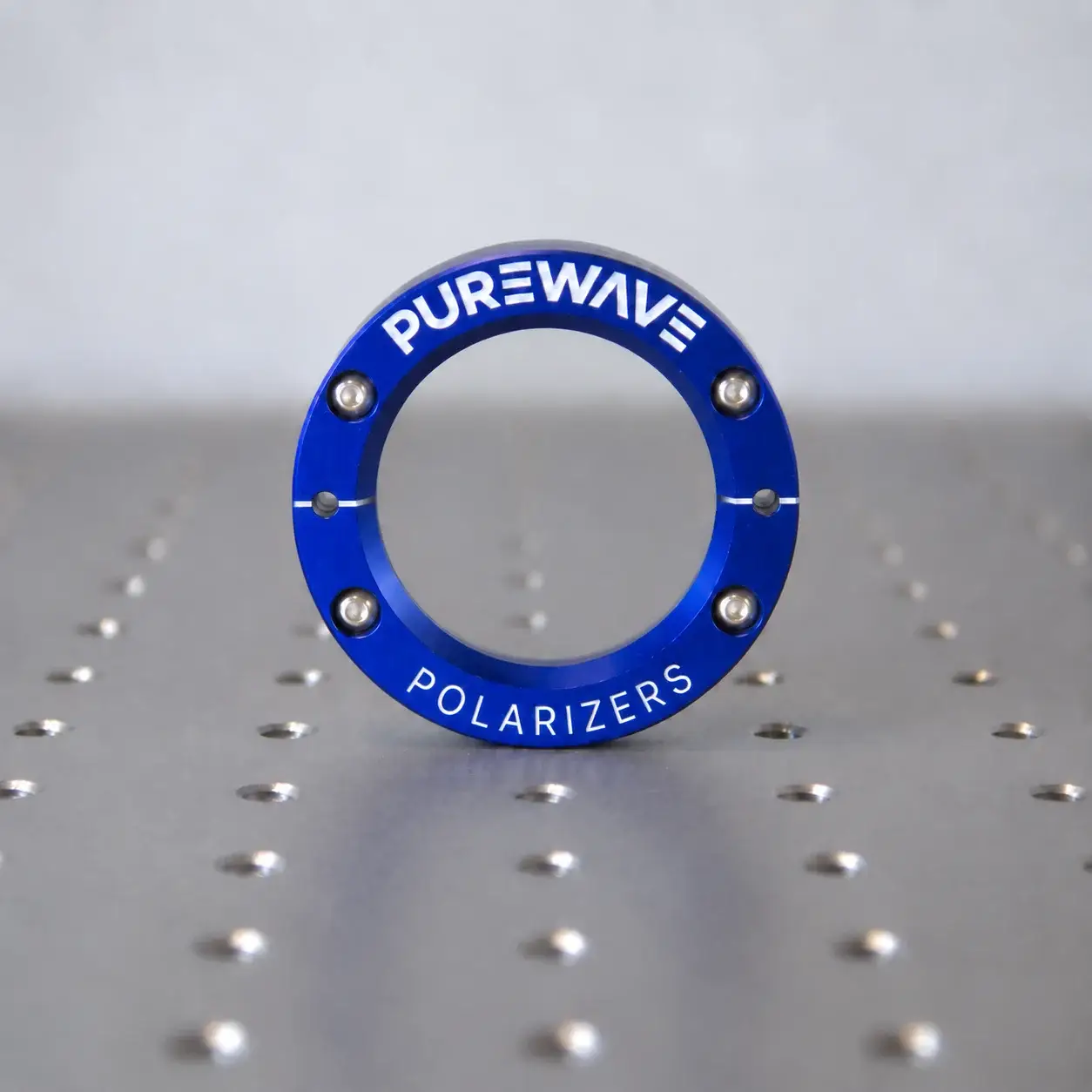
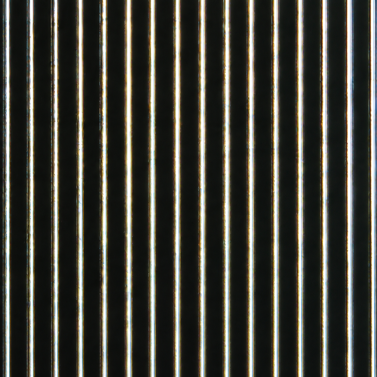
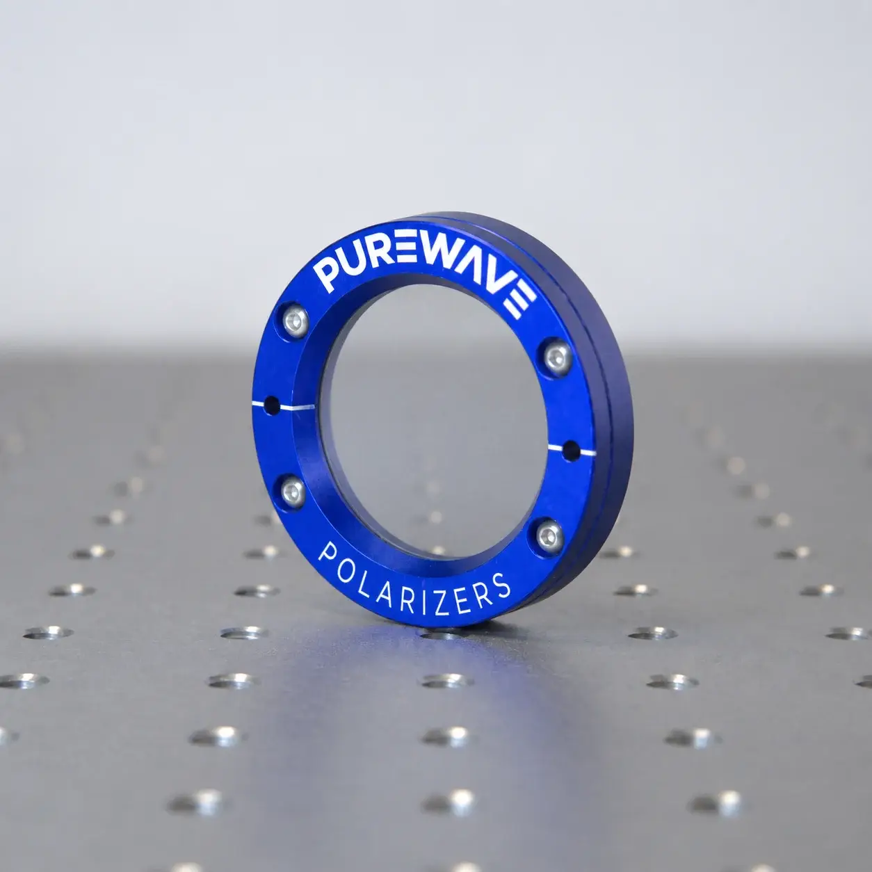
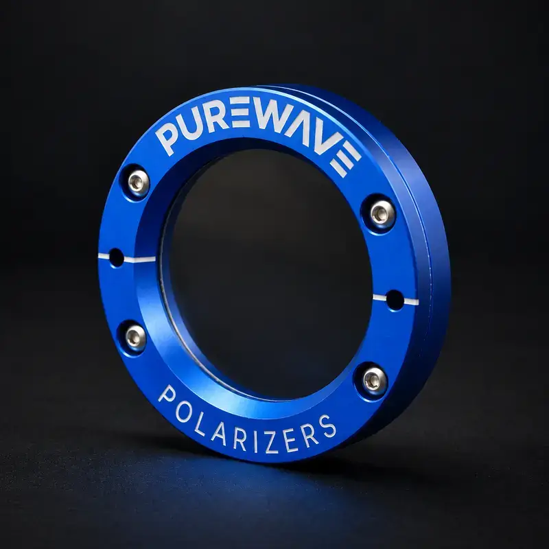







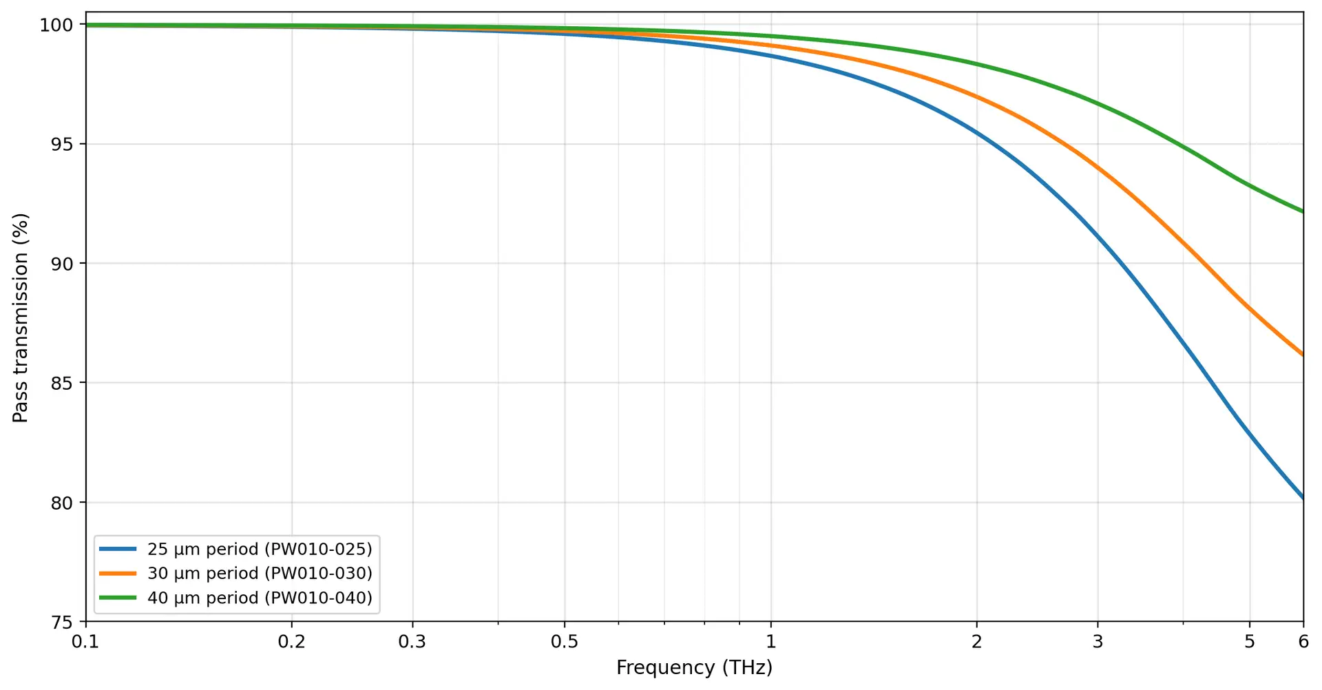
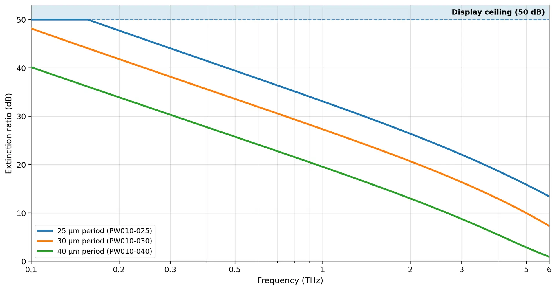


Purewavepolarizers 10 µm wire-grid polarizers are precision, free-standing components for terahertz and far-infrared systems. The PW010 series uses 10 µm tungsten wire with a choice of 25, 30 or 40 µm wire periods. The recommended operating range depends on the selected period and extends from 0.1 THz up to 4 THz for the finest grid.
The substrate-free construction avoids absorption, dispersion and beam deviation from a support film. The grid transmits the electric field perpendicular to the wires and predominantly reflects the parallel field, providing control of transmitted and reflected polarisation. Standard circular frames offer clear apertures for a range of beam diameters and optical layouts; custom grids and frames are available on request.
The datasheet summarises the available configurations, mechanical drawings and period-specific recommended operating ranges.
Free-standing tungsten wire-grid polarizers for terahertz photonics. Select a standard configuration below or request a custom option using the quote system.
family operating range
tungsten (W)
wire periods
(no substrate)
| Frequency | 25 µm period | 30 µm period | 40 µm period | |||
|---|---|---|---|---|---|---|
| THz | Pass Transmission (%) | Extinction Ratio (dB) | Pass Transmission (%) | Extinction Ratio (dB) | Pass Transmission (%) | Extinction Ratio (dB) |
| 0.1 | >99.9% | >50 dB | >99.9% | 48 dB | >99.9% | 40 dB |
| 0.3 | 99.8% | 44 dB | 99.9% | 38 dB | 99.9% | 30 dB |
| 0.5 | 99.6% | 39 dB | 99.7% | 34 dB | 99.8% | 26 dB |
| 1 | 98.7% | 33 dB | 99.1% | 27 dB | 99.5% | 20 dB |
| 3 | 91% | 22 dB | 94% | 16 dB | 97% | 9 dB |
| 6 | 80% | 13 dB | 86% | 7 dB | 92% | 1 dB |
Performance is specified for normal incidence. Actual performance may vary with alignment, system configuration and component tolerances. For application-specific guidance, please contact us.
| Parameter | PW010-025-XXX | PW010-030-XXX | PW010-040-XXX |
|---|---|---|---|
| Wire material | Tungsten (W) | Tungsten (W) | Tungsten (W) |
| Wire diameter | 10 µm | 10 µm | 10 µm |
| Wire period | 25 µm | 30 µm | 40 µm |
| Recommended frequency range | 0.1–4 THz | 0.1–2.5 THz | 0.1–1.1 THz |
| Polarizer construction | Free-standing wire grid | Free-standing wire grid | Free-standing wire grid |
| Substrate | None | None | None |
| Frame material | Anodised aluminium | Anodised aluminium | Anodised aluminium |
| Standard outer diameters | 25, 50, 75, 100, 125, 150 mm | 25, 50, 75, 100, 125, 150 mm | 25, 50, 75, 100, 125, 150 mm |
| Standard clear apertures | 14, 34, 56, 80, 100, 124 mm | 14, 34, 56, 80, 100, 124 mm | 14, 34, 56, 80, 100, 124 mm |
| Mounting holes | 2 off — see drawings | 2 off — see drawings | 2 off — see drawings |
| Overall thickness | Size dependent — see drawings | Size dependent — see drawings | Size dependent — see drawings |
Transmission and extinction ratio vary with frequency and configuration. See Performance Data for expected normal-incidence performance. For further technical information or custom configurations, please contact us.
| Part Number | Outer Diameter / Clear Aperture | Appearance | 3D Model (STEP) | General Arrangement Drawing (PDF) |
|---|---|---|---|---|
| PW010-XXX-025 | 25 mm / 14 mm | ![]() | Download STEP | Download PDF |
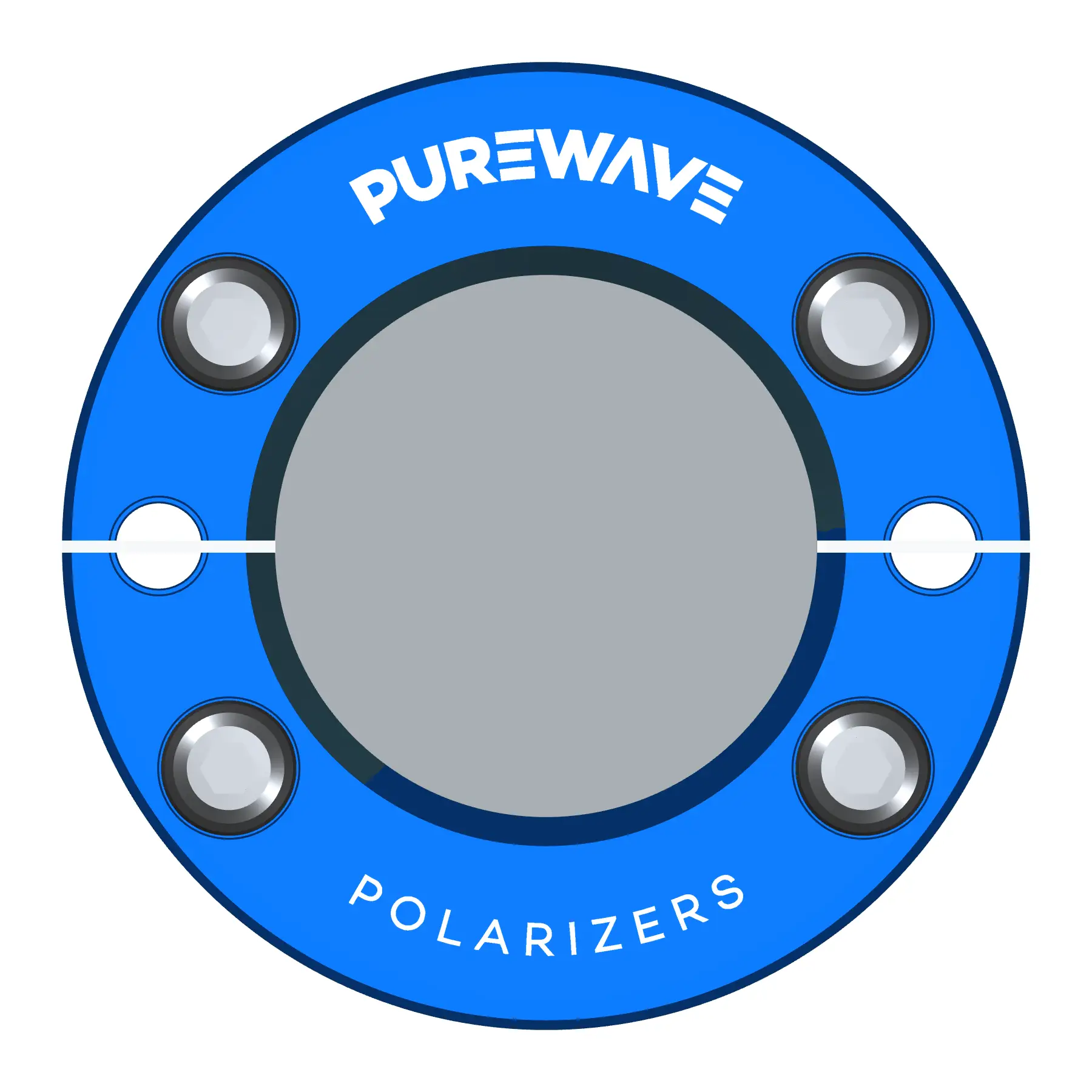
| PW010-XXX-050 | 50 mm / 34 mm | ![]() | Download STEP | Download PDF |
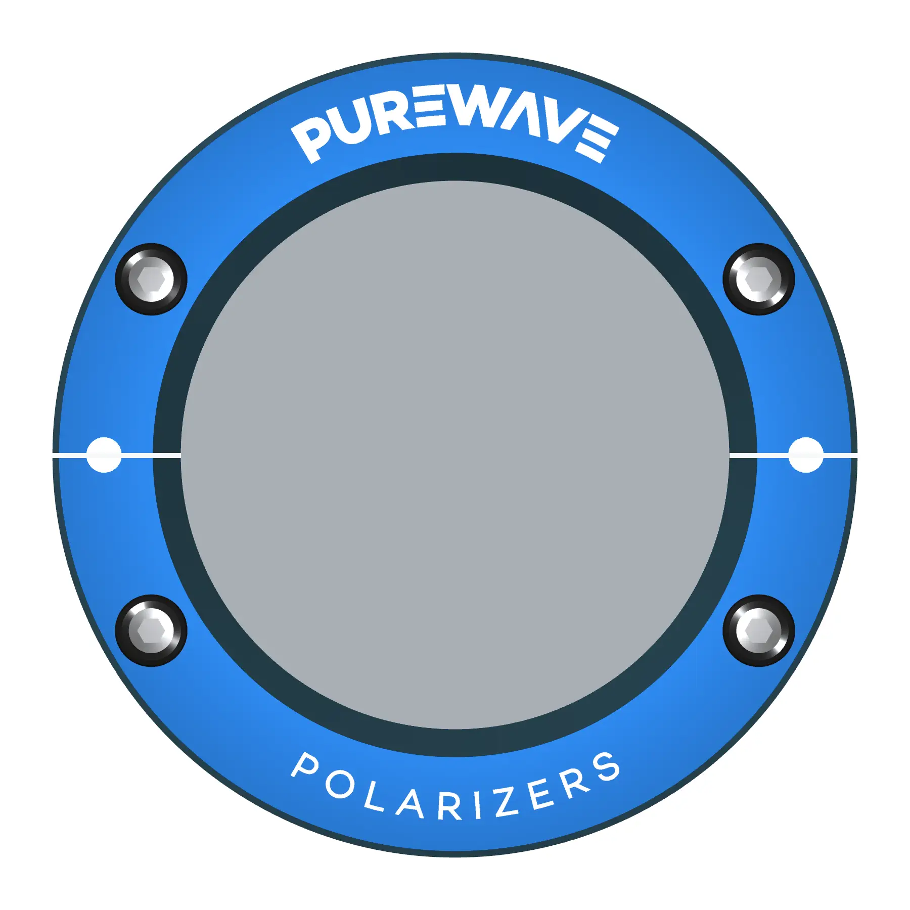
| PW010-XXX-075 | 75 mm / 56 mm | ![]() | Download STEP | Download PDF |
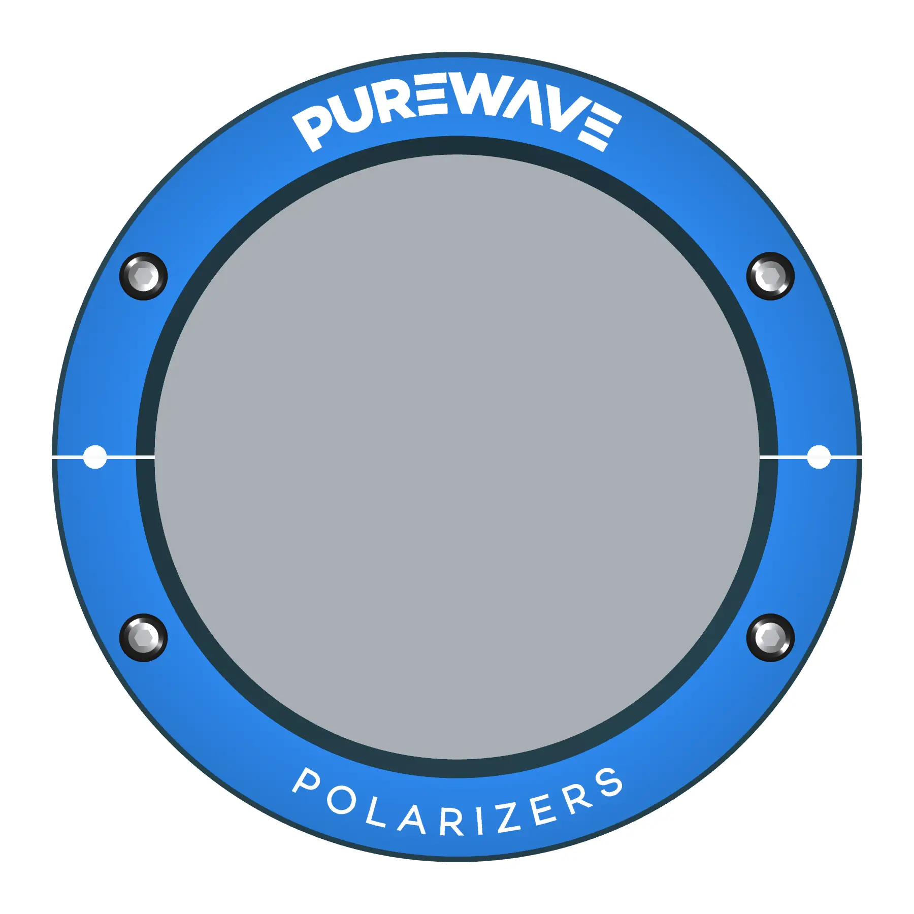
| PW010-XXX-100 | 100 mm / 80 mm | ![]() | Download STEP | Download PDF |
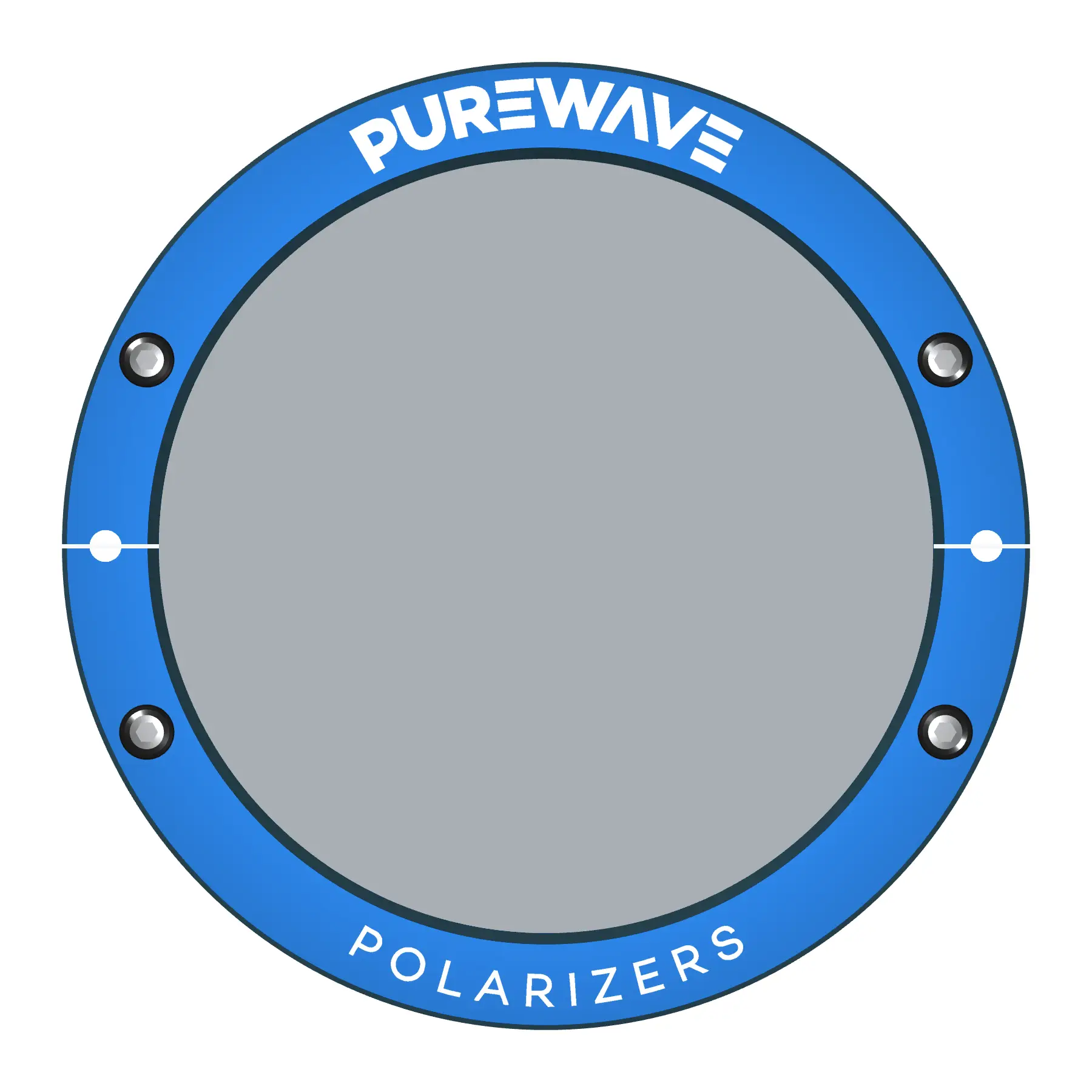
| PW010-XXX-125 | 125 mm / 100 mm | ![]() | Download STEP | Download PDF |
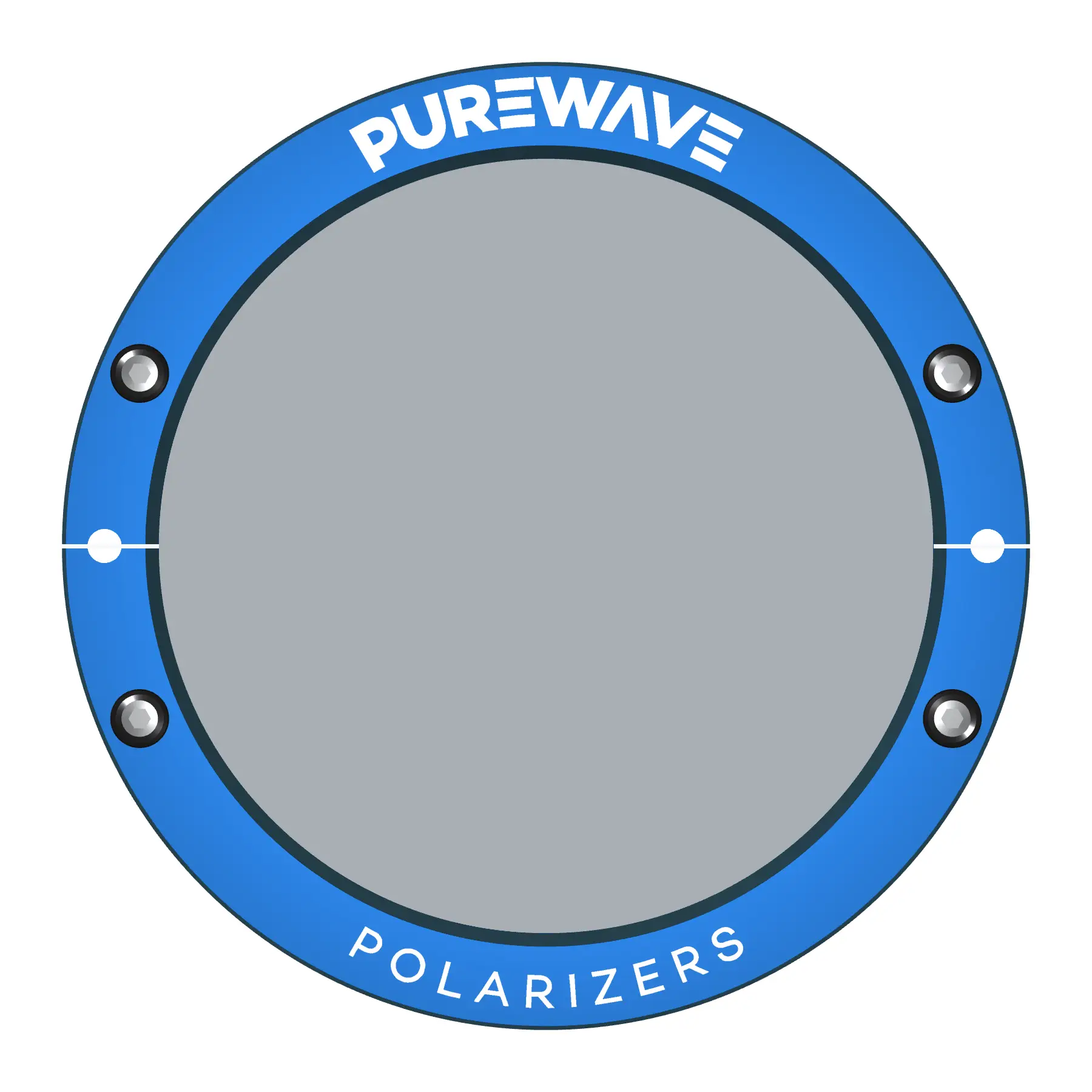
| PW010-XXX-150 | 150 mm / 124 mm | ![]() | Download STEP | Download PDF |