
THz wire-grid polarizers at 45° incidence
Practical guidance on orientation, expected performance and installation at oblique incidence.
This normally maintains or modestly improves transmission and extinction. Rotating across the wires can reduce performance.
The direction of rotation matters
A free-standing wire-grid polarizer can be used at 45° incidence in two different orientations. The rotation axis relative to the wires determines how strongly the incident field couples to the grid.
Rotate about the wires
Preferred
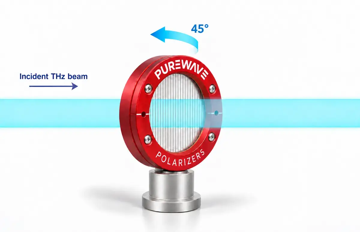
Projected pitch reduces to p cos 45°. Transmission and extinction are normally maintained and may improve modestly.
Rotate across the wires
Less favourable
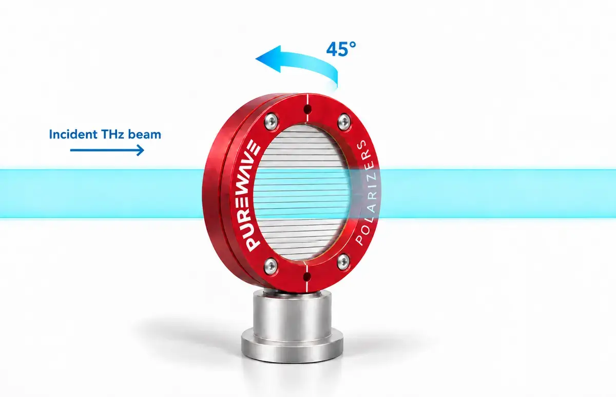
Coupling to the wire-parallel electric field is reduced. Transmission and extinction performance can decrease.
What changes at 45°?
| Property | About the wires | Across the wires |
|---|---|---|
| Projected pitch | p cos θ — appears denser | p — unchanged |
| Coupling to rejected field | Maintained | Reduced |
| Transmission extinction | Usually maintained or modestly improved | Can degrade |
| Recommended for transmission | Yes | Only where mechanically necessary |
Expected product performance at 1 THz
1 THz provides a useful common reference across all six configurations. Complete frequency-dependent performance data are provided in the relevant product datasheets.
| Product | Period | Normal Tp | Normal ER | 45° about Tp | 45° about ER | 45° across Tp | 45° across ER |
|---|---|---|---|---|---|---|---|
| PW005-012 | 12.5 µm | 99.53% | 35.9 dB | 99.67% | 38.9 dB | 99.34% | 32.9 dB |
| PW005-016 | 16 µm | 99.71% | 30.4 dB | 99.79% | 33.3 dB | 99.58% | 27.5 dB |
| PW005-022 | 22 µm | 99.82% | 23.2 dB | 99.88% | 26.0 dB | 99.75% | 20.4 dB |
| PW010-025 | 25 µm | 98.67% | 33.1 dB | 99.05% | 36.1 dB | 98.12% | 30.1 dB |
| PW010-030 | 30 µm | 99.10% | 27.3 dB | 99.36% | 30.2 dB | 98.73% | 24.4 dB |
| PW010-040 | 40 µm | 99.49% | 19.5 dB | 99.64% | 22.3 dB | 99.28% | 16.9 dB |
How to use these values. They are expected typical values rather than individually certified limits. Performance remains frequency- and configuration-dependent.
Practical installation
The projected-pitch and field-coupling explanations describe the expected trend. Quantitative angular behaviour—particularly in reflection—requires rigorous diffraction modelling or measurement in the final optical arrangement.